Fiber optics in Florida grows as Fibertronics expands by 10,000 square feet at its Melbourne location and adds new division to build metal-box enclosures that house fiber optics.

The technology sector of the small-business market, especially, it seems, located in a hub around the North Drive area in Melbourne, is buzzing with growth. And some of these businesses have taken giant steps expanding their square footage, which means their employment base is growing, they are creating jobs, and their product is being well received by their customers. Existing small businesses and startups are the economic engine in America.
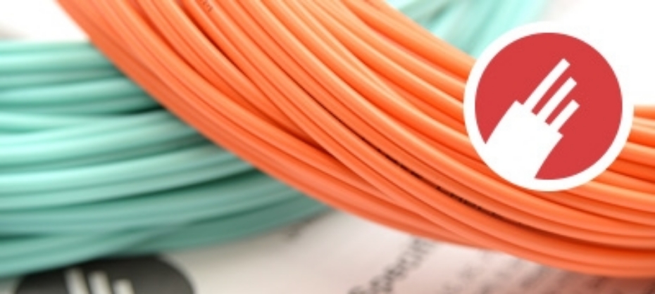
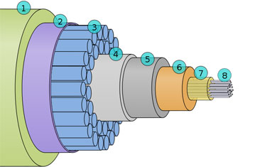
Fibertronics, which specializes in fiber-optic cable assemblies for the telecommunications industry as well as network products, is an example of a small business that has cut a path of success since it was started five years ago by area entrepreneurs Doug and Barbara Larson.
They saw a niche locally and created a company to fill it. Their business has grown from their two-car garage to 25,000 square feet at a facility on North Drive owned and managed by West Melbourne-based CIA Developers Inc. "We started in our garage and my wife was the 'terminator,' the person who terminates or builds the cables," said Doug Larson.
"Soon, our daughter started helping, as did our son. Then one of our daughter's friends came aboard the operation. The business was growing. We said 'this is not going to fit in the garage anymore.' We also had some personal belongings stored there, so we rented a 2,000 square-foot building." After one year in that building, Fibertronics needed more space and rented another 4,000 square feet. The business outgrew that space, too.
Doug Larson said he then contacted Aaron Anderson of CIA Developers. Anderson showed him a 15,000 square-foot building on North Drive. It's one of a number of facilities CIA Developers owns in that area. Fibertronics moved in and set up its operation.
Recently, the company leased another 10,000 square feet that is connected to the original unit that CIA Developers owns, bringing Fibertronics to 25,000 square feet at the North Drive facility. "We have doubled our business every year over the last five years and we're on track to do it again," said Doug Larson, whose company has grown from two to 27 people, including their son Mitchel Larson and their daughter Evelyn Vogt.
"We pride ourselves on quick turnaround, short lead times, and we are really pushing quality." He added that the company is growing at a "steady pace and we don't see any signs that it's going to slow down. Our growth is based on the Internet's growth. And the Internet is still growing at a radical rate. The Internet runs on fiber optics. So I would say the key to the success and growth of our company is the performance of the industry, which is fiber-optic communications."
According to the "Accenture Technology Vision 2015" report, in the rapidly growing "Internet of Things," companies are using "digital ecosystems" to offer new services, reshape experiences, and enter new markets. By 2020, there will be a "quarter billion" connected vehicles on the road, enabling new in-vehicle services and automated driving capabilities, according to Gartner Inc. During the next five years, the proportion of new vehicles equipped with this capability will increase dramatically, making connected cars a major element of the Internet of Things.
Gartner forecasts that 4.9 billion "connected things" will be in use in 2015, up 30 percent from 2014, and will reach 25 billion by 2020.
John Chambers, the president and chief executive officer of Cisco Systems, said in a speech at the Consumer Electronics Show in Las Vegas that he sees the value of the evolving Internet of Things at $19 trillion, and gave a number of examples in support of his forecast.
Meanwhile, Fibertronics is well positioned to grow because its core customers include Fortune 200 companies that purchase in big volume from the company. "They tell us what they want, and we custom build it for them," Doug Larson said.
Doug Larson has owned a number of service-type businesses over the years. One day, he learned there were defense contractors in the region wanting to buy fiber-optic cables in a more timely fashion than what was currently available. Companies were having to wait a month or longer. "Coming from a service-business background, I couldn't imagine taking a month or so to do anything. So I started looking into what is involved in building fiber-optic cables." He continued, "Yes, it is kind of intense. But it takes hours to build a cable, not months. That's when I said, 'I think I have something.' Now we build cables for many defense contractors, though that is not our core customer."
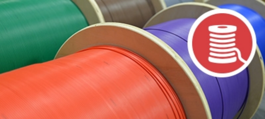
Fibertronics, whose customers are mainly from out the state, builds small cables that have a lot of power because they contain fiber optics. "For example, we build 40 gigabyte and 100 gigabyte cable assemblies. We'll build as many as 1,000 cables a day. That's normal. We constantly strive to stay on the cutting edge of quality." Barbara Larson is a hands-on businesswoman with an eye on quality. "I like to build the cables in the back of the facility and work right among the employees to make sure everything flows smoothly." Fibertronics hired at least 10 people last year and three more recently. "We try to provide our employees with very good benefits because we want to retain them. They can grow along with company," she said. "We pay 100 percent of our employees' health insurance," added Doug Larson, "and that has nothing do with the mandated Affordable Care Act. We don't want turnover, which is costly to a business. We like to train new hires the company's way and give them the opportunity to advance up the ranks."
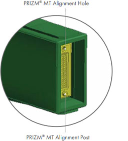
As it continues to grow, Fibertronics has expanded with a new division dedicated to building sheet-metal boxes - known in the industry as "enclosures"- that house the fiber optics. "A lot of the fiber-optics assemblies we build are installed in these metal boxes," he said. "So now, we are starting to make those cabinets for customers. We can now offer them a full network solution, including the fiber, all of the adapters, and so forth." He added, "When we ship the product and they receive it, all the customer has to do is plug it in." With the new division, Fibertronics has positioned itself to be a full-service firm. The company has made a significant investment in new machinery to build the enclosures and be able to offer a customized solution for its customers. "The customer can call one company - Fibertronics - and we're able to provide them with a whole solution. This new division fits perfectly with our core product and our market niche," Doug Larson said.
Brevard Business News


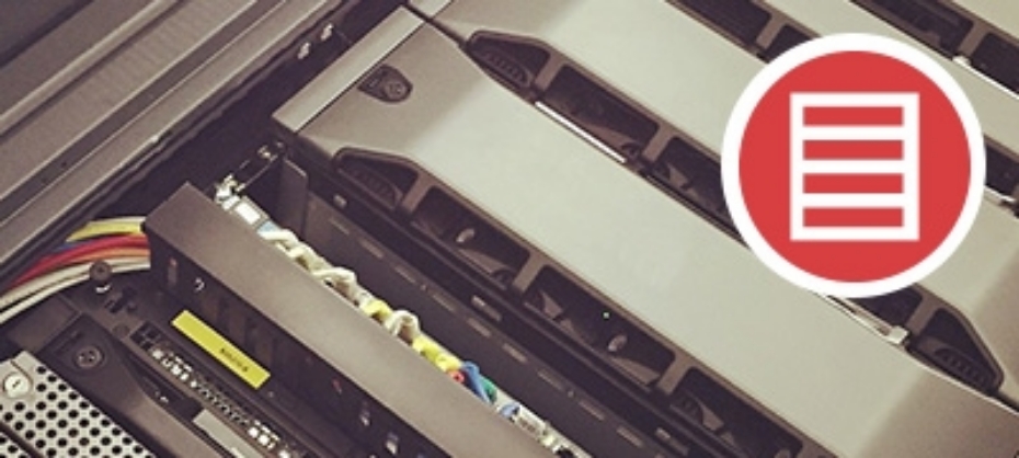


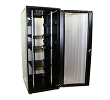 Rack Enclosure – Floor Standing
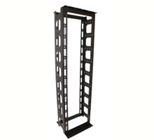 Open Frame – Floor Standing
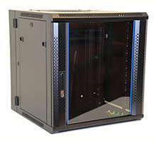 Rack Enclosure – Wall Mount
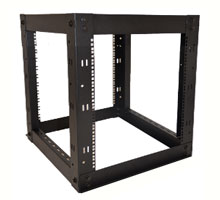 Open Frame – Wall Mount
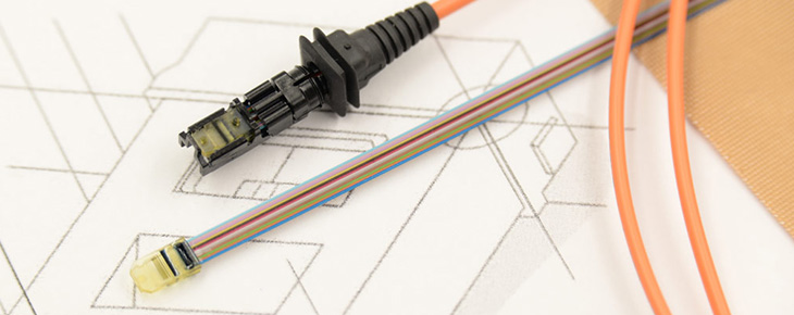
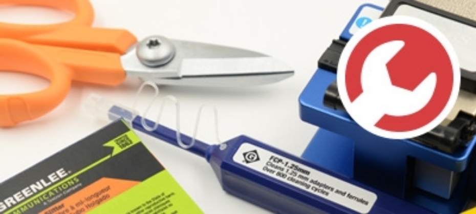
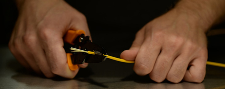
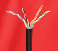 To start off with you will want to begin with preparing the cat cables you intend to punch into the patch panels. You with do so by removing the outer jacket with the cable stripper. If you do not have a cable stripper handy it can also be done with a sharp knife, but please be careful as this method result in both injury to yourself and damage to the inner copper cables.
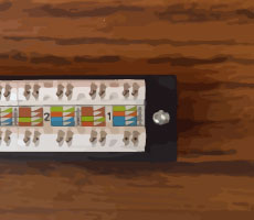 In most cases full patch panels are made up various parts. That being said, it can prove very useful in most situations to break apart the patch panel into it’s small components. This allows for you to work with only the required parts of the panel and makes the entire project simpler to handle on the whole.
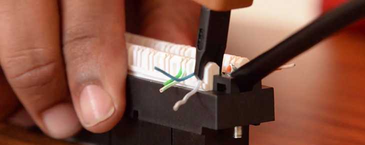
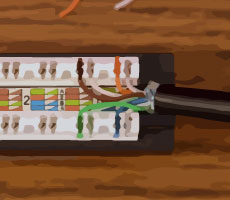 In order to correctly insert the Cat cable wires into the patch panel you will need to take a close look at the color code that is printed on the label adhered to the panel.Let’s take a closer look.
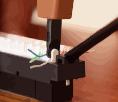 First off you will notice that there are in fact 2 pin-out types, these are typically labelled A and B respectively. Generally most installations would use pin-out B, but please be sure to check which one is right for your specific application.

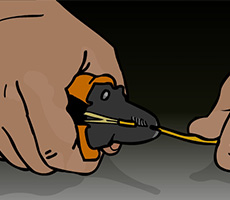 It sounds simple enough right? Unfortunately this is not quite as simple as stripping the simple coating of your average house-hold copper cable. In this case you will first be removing the polymer coating by making use of
 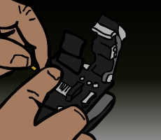 Keeping the fibers clean is of the utmost importance when it comes to fusion splicing. It cannot be repeated enough, ensure that the fibers you are working with are cleaned after every major interaction with them. You do this by gently wiping them down with Alcohol Wipes.
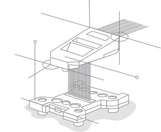
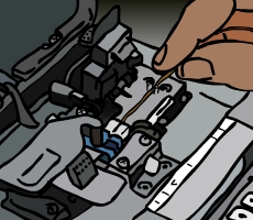 It is now time to make use of your

