


Cookies help us deliver our services. By using our services, you agree to our use of cookies.
You have no items in your shopping cart.

_1000.png)
Today’s communication technologies demand solutions that are smaller, lighter, and faster than ever before. This is evident in the widespread adoption of fiber optics in high-performance applications. At the core of these solutions are compact, reliable, and adaptable cable assemblies, which provide design engineers with the flexibility to deliver optimized performance without compromising space.
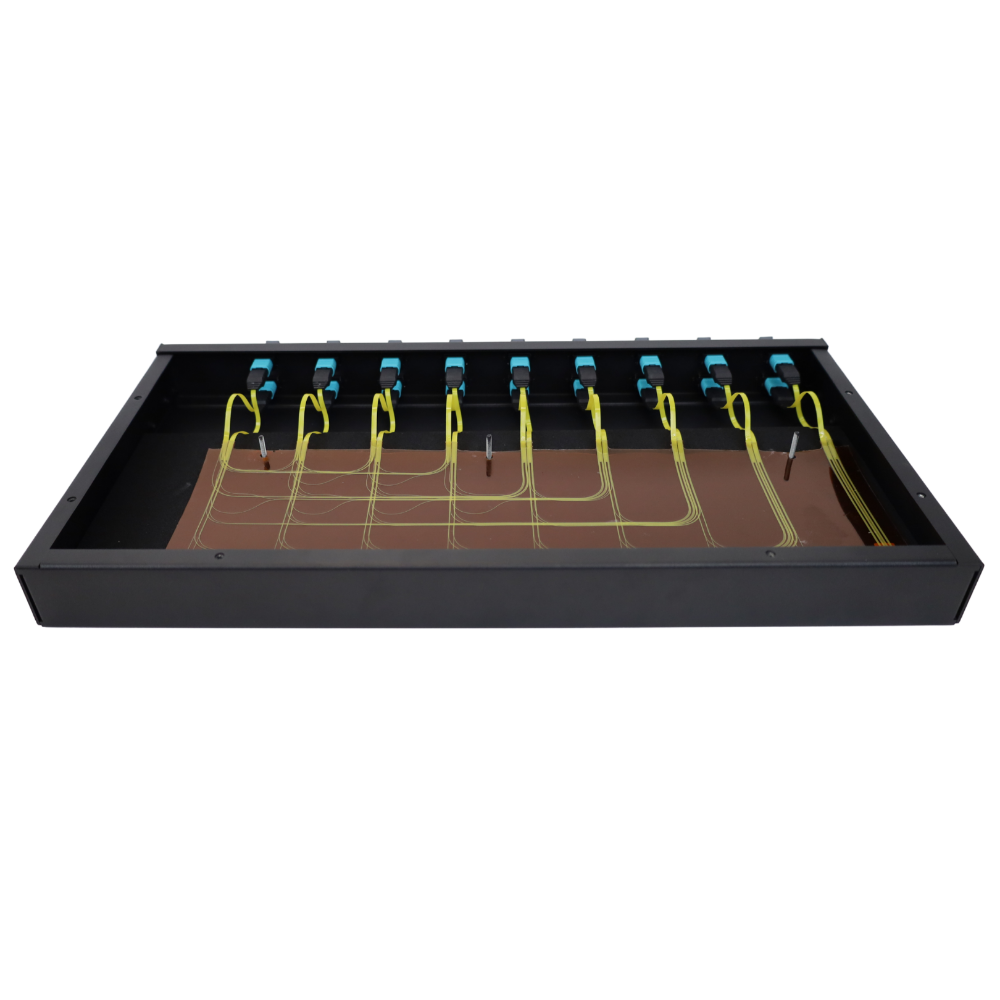 As communication systems evolve, maximizing internal airflow is more critical than ever. Fiber Optic Flex Circuit Assemblies (FOFCA) address the growing need for efficient cable management. These assemblies offer a clean, organized way to route fiber between boards, shelves, or even tight, complex spaces, ensuring both performance and spatial efficiency.
Flexibility is a key part in simplifying a system. Fiber can be configured in nearly any routing layout, whether point-to-point, shuffled, or in predefined patterns—to accommodate the specific needs of a given application.
FOFCA is manufactured based on custom design files, defined parameters, and application-specific requirements, allowing precise and space-efficient fiber routing within the system.
The use of polyimide materials and conformal coating adhesives ensures robust fiber protection, meeting the stringent durability requirements of harsh industrial environments.
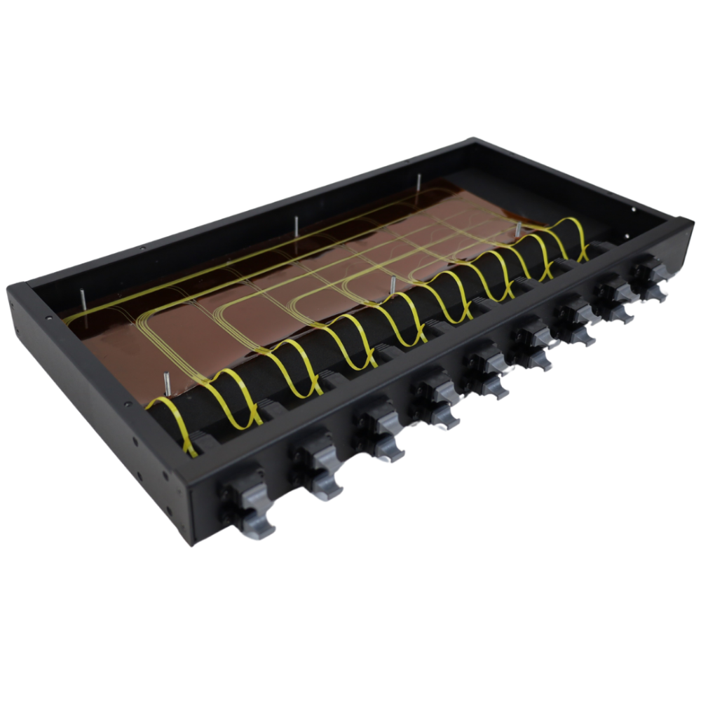
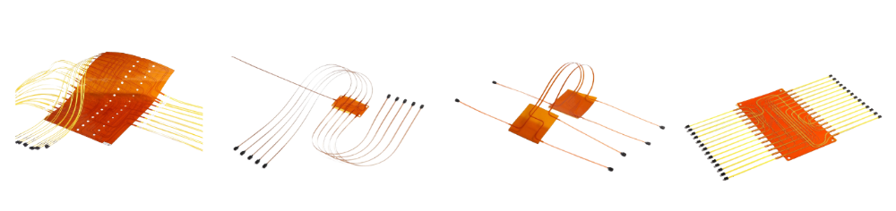
The fiber circuit is mainly composed of four parts: adhesive substrate, optical fiber, coating glue and a termination connector. Substrate size & shape, fiber type, channel number, fiber leading-out form, connector type, fiber path, and optical cross relationship are some of the specs that can be customized upon demand.
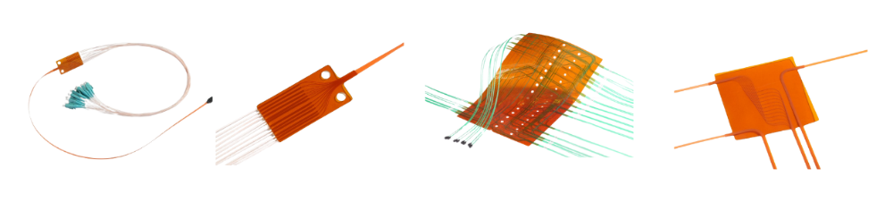
Flex circuits can be terminated with a wide range of industry-standard connectors including MTP, MXC, LC, and SC. They also can be provided unterminated, allowing optical terminations to be applied as needed. Circuit dimensions range from just a few millimeters in width to large, complex sheets up to 1,760 square inches. Typically, 500mm x 500mm substrate can accommodate over 300 fibers.
A single-layer optical plane can support anywhere from a few to several hundred or even thousands of channels. To further increase capacity, fiber channels can be multiplied through stacking, which is typically achieved using two primary stacking methods.
Features & Benefits
Applications
Technical Specifications
| Terminations Supported | MTP, MPO, MT ferrules, LC, SC, MXC, MDC, MMC, etc. |
| Position Accuracy On Substrate | ±0.01mm |
| Fiber Modes Supported | Singlemode, Multimode, and Hybrid versions |
| Fiber Diameter | 250μm and Special Fibers |
| Material | Optical Fiber Protection: Conformal Coating Substrate: Polyimide |
| Operating Temperature | -40°C to +85°C |
| Maximum Size | 950 mm x 1200 mm |
| Substrate Size Tolerance | ± 3mm 300 fibers (500mm x 500mm substrate) |
| Optical Performance | <0.1dB loss (excluding connector) |
Fibertronics, Inc. is in compliance with AS9100D and ITAR certifications, has been officially assessed by NSF-ISR. Our plenum rated (OFNP) assemblies meets NEC 770 compliance and standards. Custom cable assemblies are in compliance with EIA-455-171, FOTP-171, NECA-FOA-301, and IEC 61280-4-5 testing standards.

Help others like you find us by leaving us a review on Google

We improve our products and advertising by using Microsoft Clarity to see how you use our website. By using our site, you agree that we and Microsoft can collect and use this data. Our privacy statement has more details.